
A Lazy Computer Science Student's Guide To Building An Adding Machine
February 10, 2024
I've been engrossed in reading Code - The Hidden Language of Computer Hardware and Software by Charles Petzold for the past few days. Recently, I stumbled upon a chapter that finally clarified what my CSC 313 (Introduction to Design of Digital Systems) lecturer has been attempting to convey for a little over three months – how computers work. It was an ‘aha!’ moment for me, and now I'm excited to share with you what I've learned. I'll show you how to construct an Adding Machine – a fundamental model of computation. However, we won't be building a physical one (mostly because I can't afford it). Instead, we'll create it in our minds and on paper. Let's delve into it.
Disclaimer: The adding machine we're about to construct may seem rudimentary (think 1800s technology), as we're just starting to unravel these concepts and it will only be capable of adding 8-bit binary numbers.
Prerequisites
To follow along with this tutorial, it's important to have a basic understanding of binary numbers (what they represent and their significance in computing) and logic gates.
Binary Numbers
Let's revisit binary numbers for a moment. They are a base-2 number system, which means they use only two digits: 0 and 1. Unlike the familiar base-10 (decimal) system, which uses ten digits (0 through 9), binary numbers represent values using powers of 2.
Binary numbers are commonly used in digital computing because they directly relate to the on/off states of electronic switches (0 representing off, and 1 representing on). They are essential for representing and manipulating data in computers and digital systems. Ready to proceed? Let's continue.
Logic Gates
To construct an adding machine or any digital system, we require logic gates. These gates serve as the basic building blocks of digital circuits that perform logical operations on one or more binary inputs and produce a single binary output based on those inputs.
Logic gates lay the groundwork for digital electronics and are used to process and manipulate binary information in digital systems. There are several types of logic gates, each with its own function:
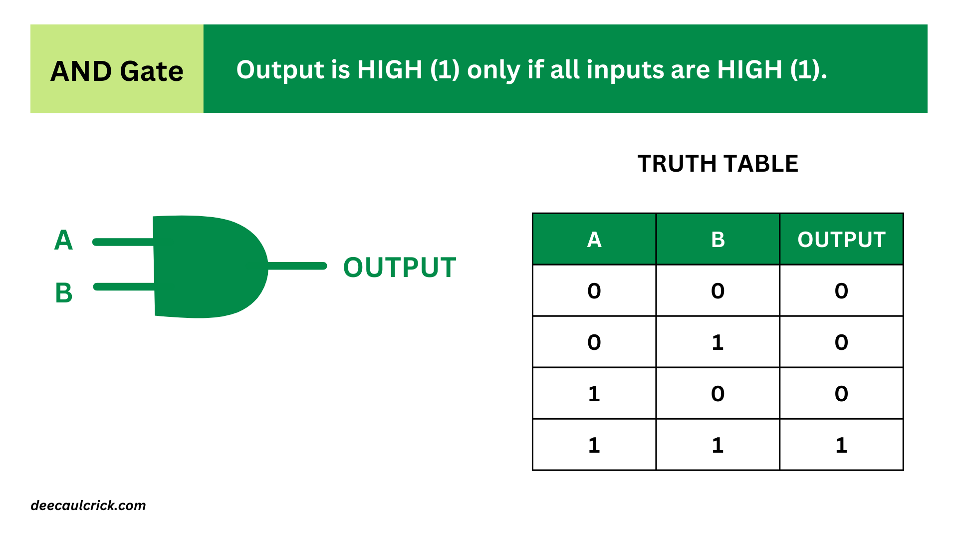
- AND Gate: An AND gate produces a HIGH (1) output only when all of its inputs are HIGH (1). Otherwise, it produces a LOW (0) output. The symbol for an AND gate is typically represented by the word "AND" or by the ∧ symbol.
- OR Gate: An OR gate produces a HIGH (1) output if at least one of its inputs is HIGH (1). It produces a LOW (0) output only when all of its inputs are LOW (0). The symbol for an OR gate is typically represented by the word "OR" or by the ∨ symbol.

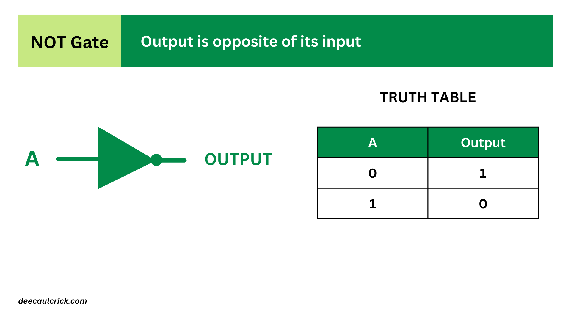
- NOT Gate (Inverter): A NOT gate, also known as an inverter, produces an output that is the opposite (complement) of its input. If the input is HIGH (1), the output is LOW (0), and vice versa. The symbol for a NOT gate is typically represented by the word "NOT" or by a triangle with a small circle at its input.
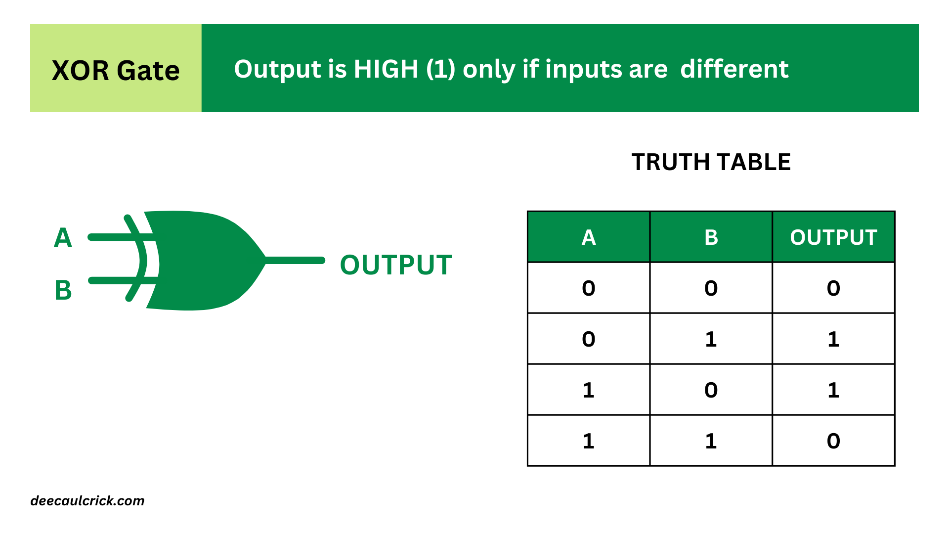
- XOR Gate (Exclusive OR): An XOR gate produces a HIGH (1) output if the number of HIGH (1) inputs is odd. Otherwise, it produces a LOW (0) output. The symbol for an XOR gate is typically represented by the word "XOR" or by the ⊕ symbol.
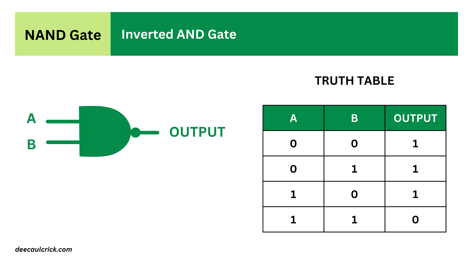
- NAND Gate: A NAND gate is the complement of an AND gate. It produces a LOW (0) output only when all of its inputs are HIGH (1), and it produces a HIGH (1) output otherwise. The symbol for a NAND gate is typically represented by the word "NAND" or by a combination of AND gate and NOT gate symbols.
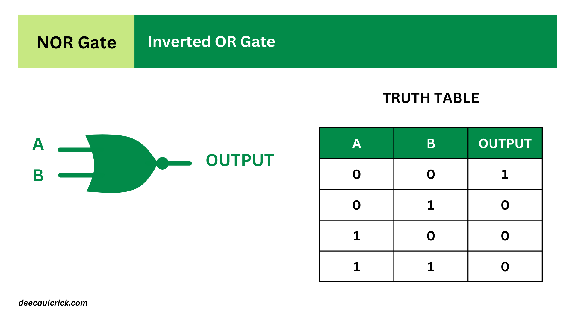
- NOR Gate: A NOR gate is the complement of an OR gate. It produces a LOW (0) output if at least one of its inputs is HIGH (1), and it produces a HIGH (1) output only when all of its inputs are LOW (0). The symbol for a NOR gate is typically represented by the word "NOR" or by a combination of OR gate and NOT gate symbols.
These logic gates are going to be combined in various ways to create more complex digital circuits, which are going to allow us to perform some arithmetic. But first, let’s figure out how binary addition works.
Binary addition and the comparison to logic gates
As I mentioned earlier, in binary, we only have two digits: 0 and 1. To add two binary numbers, start by adding the rightmost digits (also called the least significant bit) and work your way to the left, just like in decimal addition.
Here's a simple example showing how to perform the 4-bit addition of 0101 (which represents 5 in decimal) and 0110 (which represents 6 in decimal).
markdown0101

- ## 0110
- Start from the Right: Begin by adding the rightmost digits together. In this case, it's 1 + 0, which equals 1. Write down the result in the bottom row.
markdown0101

- ## 0110
  1
- Repeat the same process for the next rightmost digits. 0 + 1 equals 1.
markdown0101

- 0110

---

     11
- Dealing with Carry: If the sum of the digits in a column is greater than 1 (i.e., 2 in decimal, 10 in binary), you'll have to carry over to the next column. In this case, the sum of 1 + 1 (from the third column) equals 10 in binary, so we write down 0 in the current column and carry over the 1 to the next column.
markdown1
0101

- 0110

---

    011
- Repeat the Process: Continue adding the digits in each column, including any carried-over digits from the previous columns. Repeat this process until you reach the leftmost column.
markdown1
0101

- 0110

---

1011
- Final Result: Once you've added all the columns, you'll have the final result. In this example, the sum of 0101 and 0110 is 1011, which represents 11 in decimal.
And that's it!
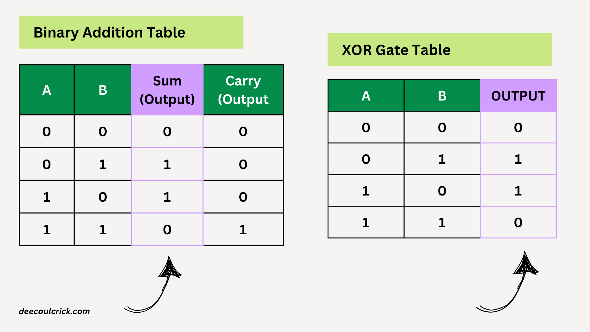
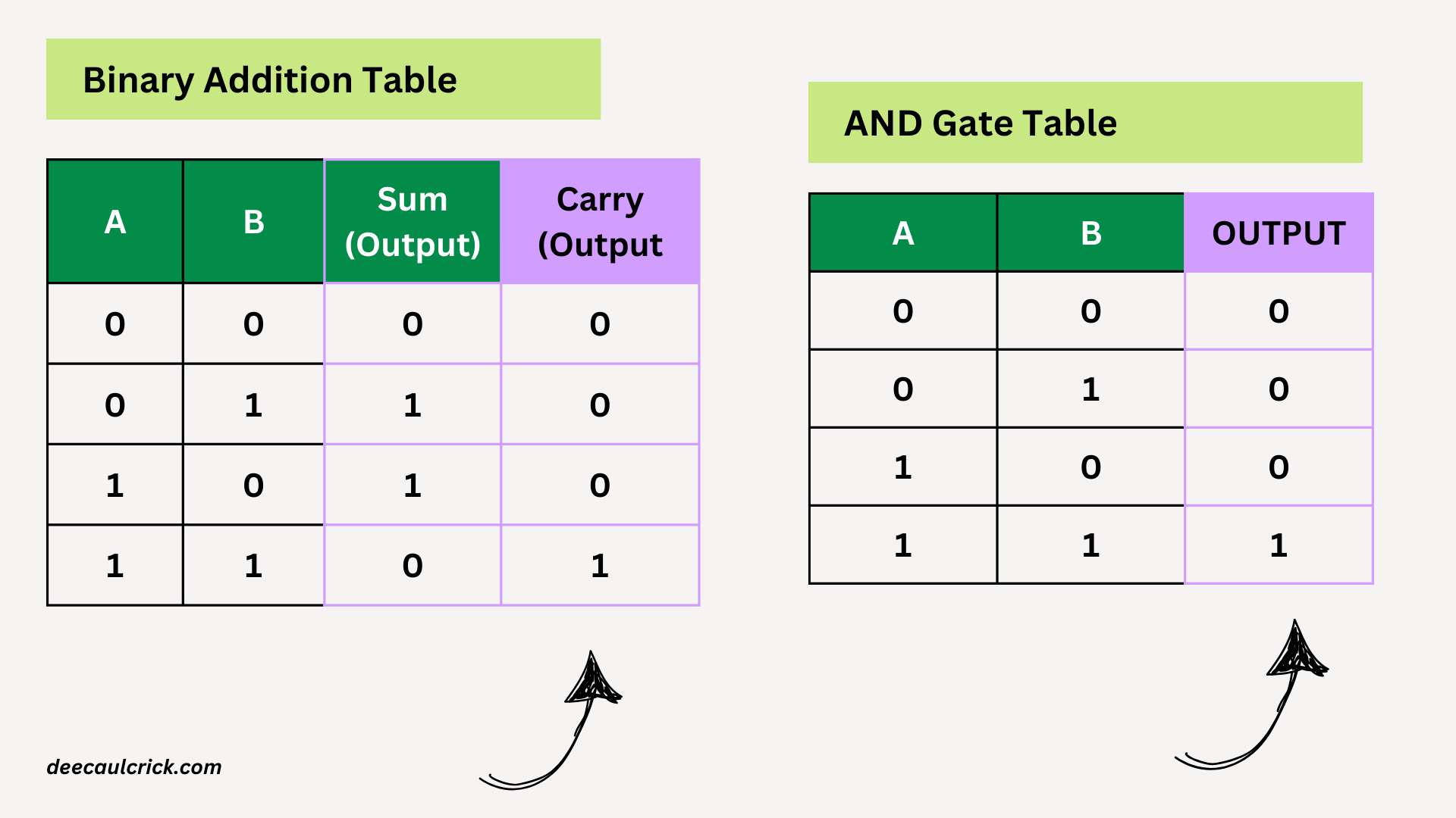
Now let’s create an addition table. We'll have two input columns (A and B) and two output columns ( for Sum and Carry bits):
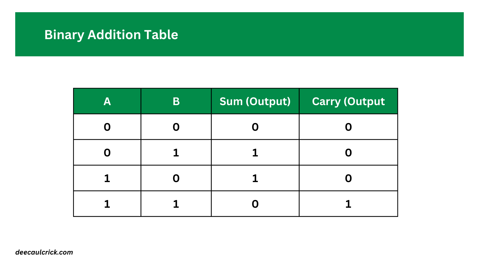
Let’s look at the Sum (Output) column. If you look closely, you’ll see that it resembles the truth table result of the XOR gate
If you look at the Carry (Output) column, you’ll see that it’s the same as the output for the AND gate.
Therefore we can perform binary addition using two gates: the AND gate and the XOR gate. The logic circuit will look like this:
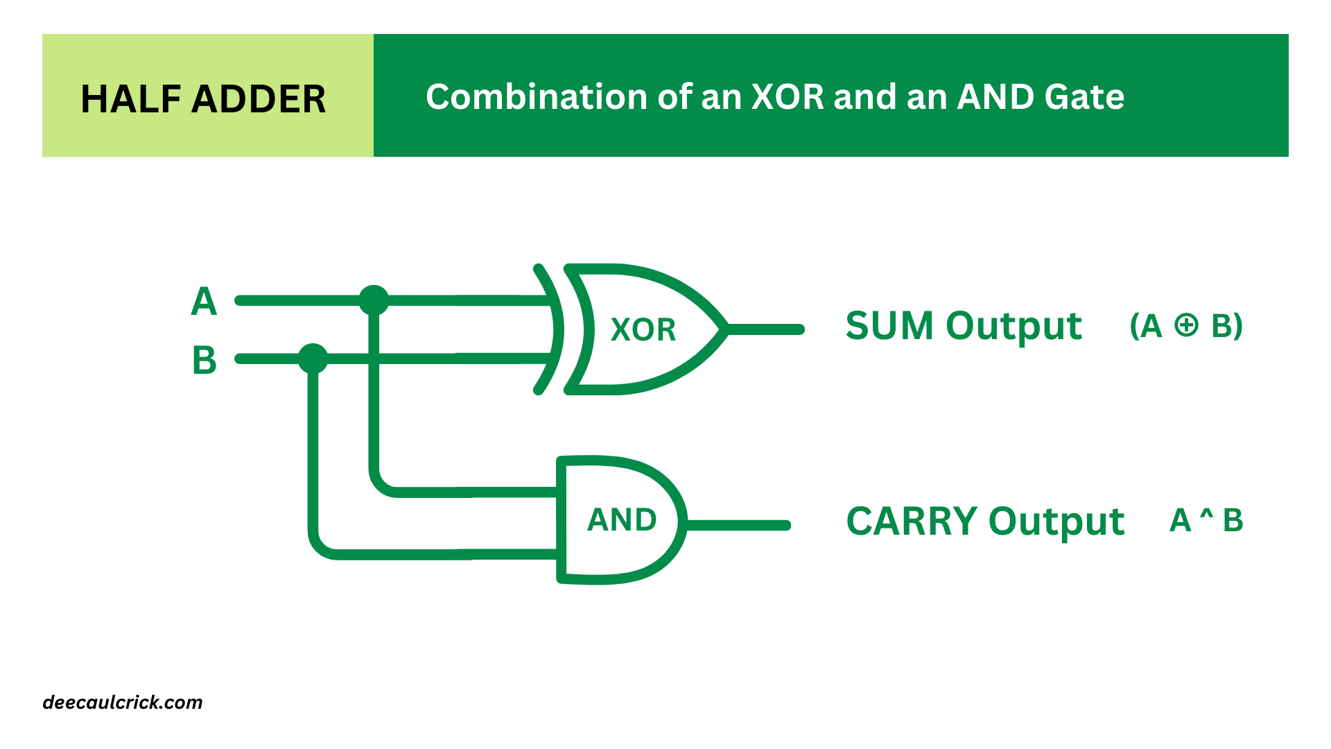
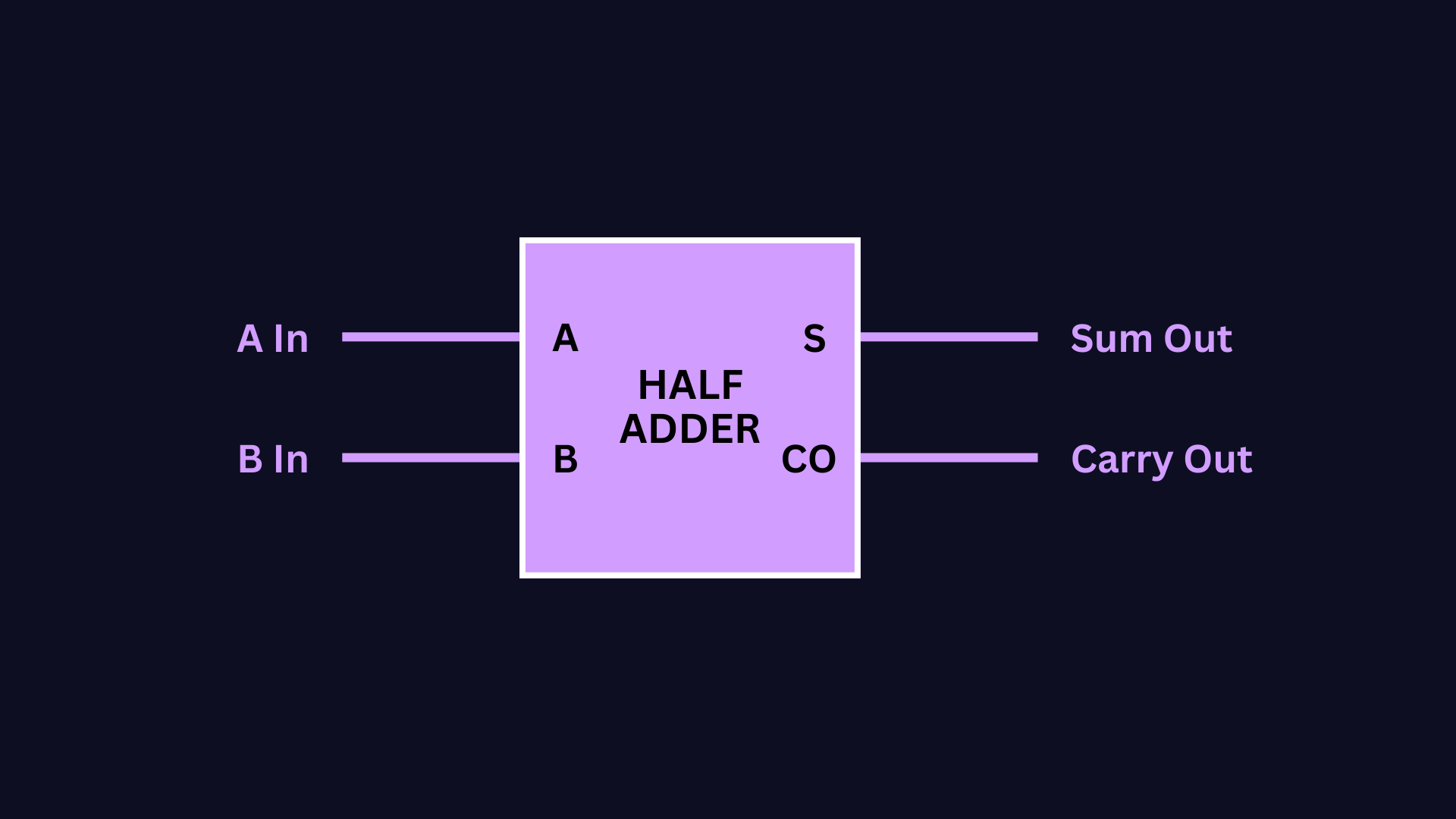
This circuit is also known as a half-adder, mainly because it only adds two binary digits. Instead of drawing and redrawing an AND gate and an XOR gate, you can simply draw a box like this:
But at some point, we’ll have to add three binary digits because there will be a case where we will have to add a carry bit.
Putting the adding machine together: half adders & full adders
To add three binary numbers, we need two Half Adders and an OR gate, wired this way:
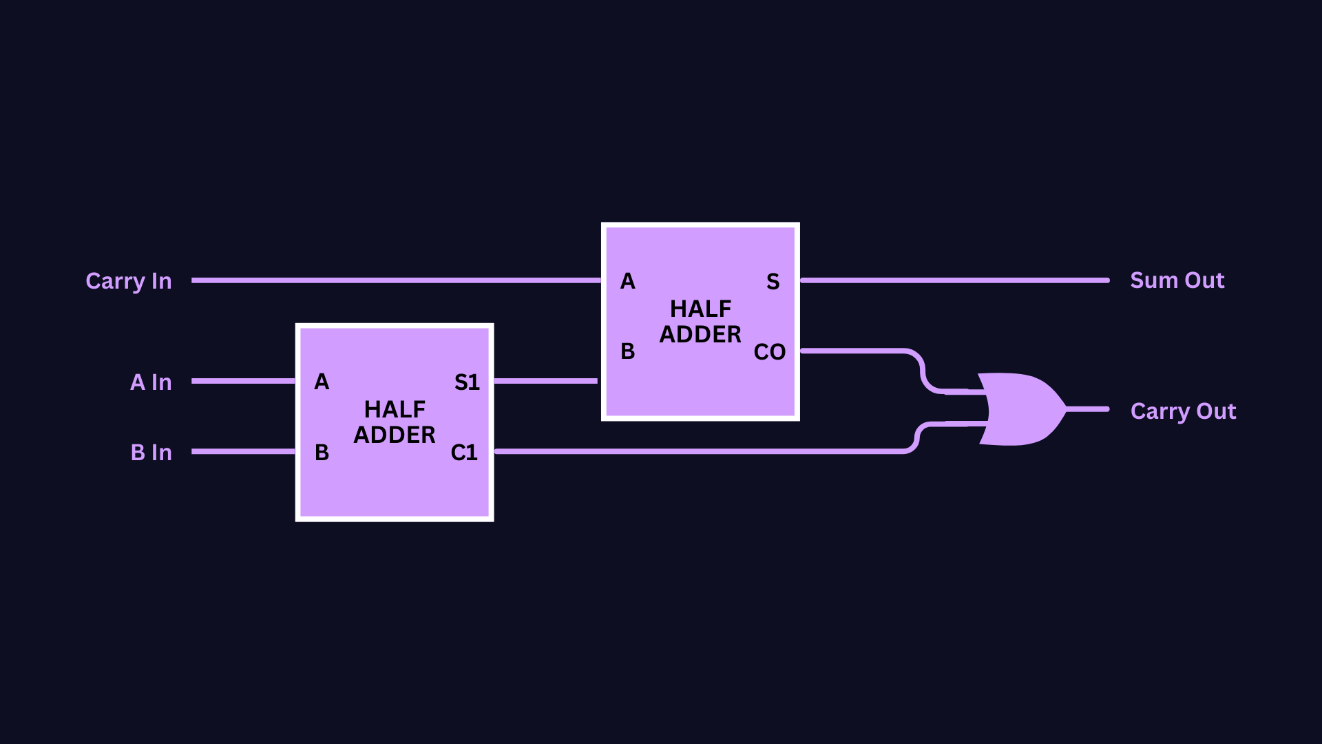
First Half-Adder: This half-adder takes two input bits, A and B. It produces a sum (S1) and a carry-out bit (C1).
Second Half-Adder: This half-adder takes the sum (S1) from the first half-adder, along with an additional input bit, C_in (carry-in). It produces the final sum (S) and a carry-out bit (Cout).
OR Gate: The output carry bit (C1) from the first half-adder and the carry-out bit (Cout) from the second half-adder are fed into an OR gate. This OR gate produces the final carry-out bit (Cout) of the full adder.
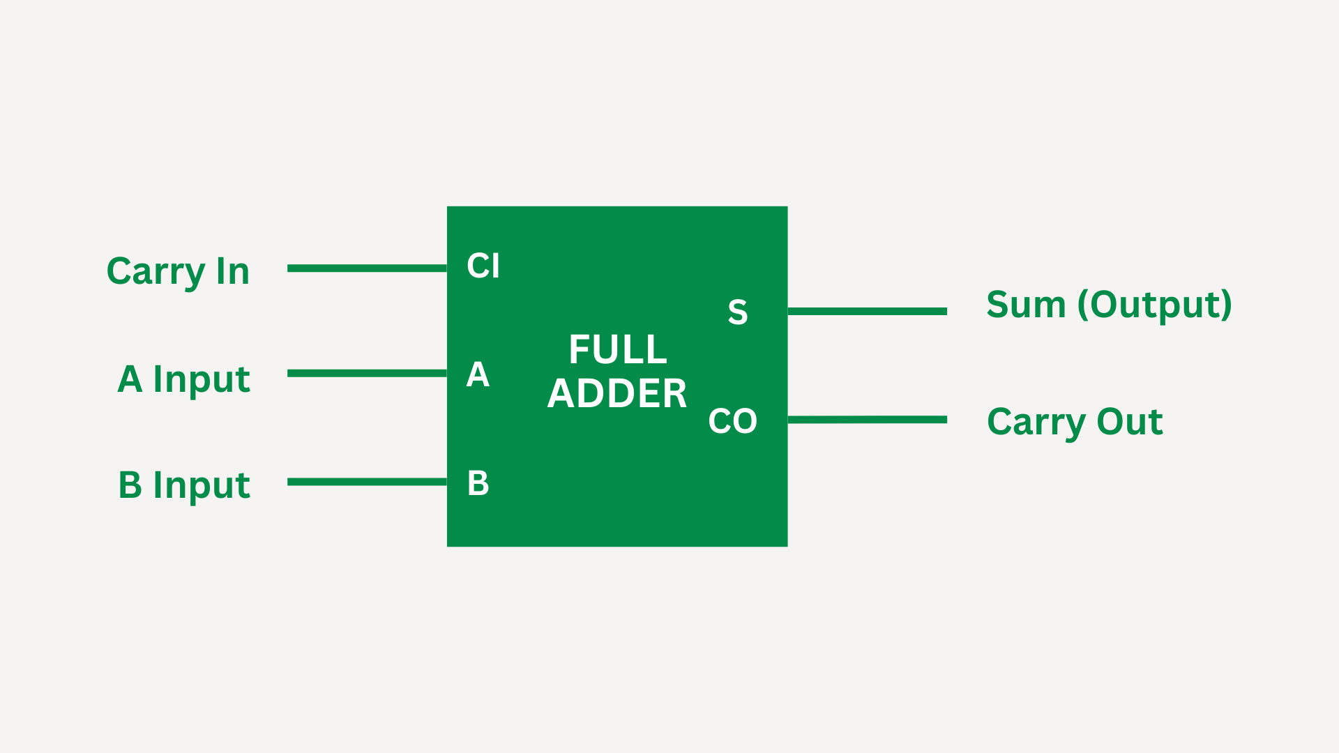
A full adder adds three binary digits: a, b, and an input carry bit (Cin), producing a sum (S) and an output carry bit (Cout).
Below is the truth table for an 8-bit full adder: (Note that the Carry(Input) is the Carry(Output from the previous stage).)
| A (Input) | B (Input) | Cin (Input) | Sum (Output) | Cout (Output) |
|---|---|---|---|---|
| 0 | 0 | 0 | 0 | 0 |
| 0 | 0 | 1 | 1 | 0 |
| 0 | 1 | 0 | 1 | 0 |
| 0 | 1 | 1 | 0 | 1 |
| 1 | 0 | 0 | 1 | 0 |
| 1 | 0 | 1 | 0 | 1 |
| 1 | 1 | 0 | 0 | 1 |
| 1 | 1 | 1 | 1 | 1 |
This truth table outlines all possible combinations of input bits (A, B, and Cin) and their corresponding output bits (Sum and Cout) for an 8-bit full adder.
By combining the outputs of two half-adders with an OR gate, we effectively create a full adder circuit capable of adding three input bits (A, B, and Cin) and producing a sum (S) and a carry-out (Cout). This complete adder circuit forms the basic building block for arithmetic operations in digital systems. Instead of drawing and redrawing 2 half-adders and an OR gate, you can simply draw a box like this:
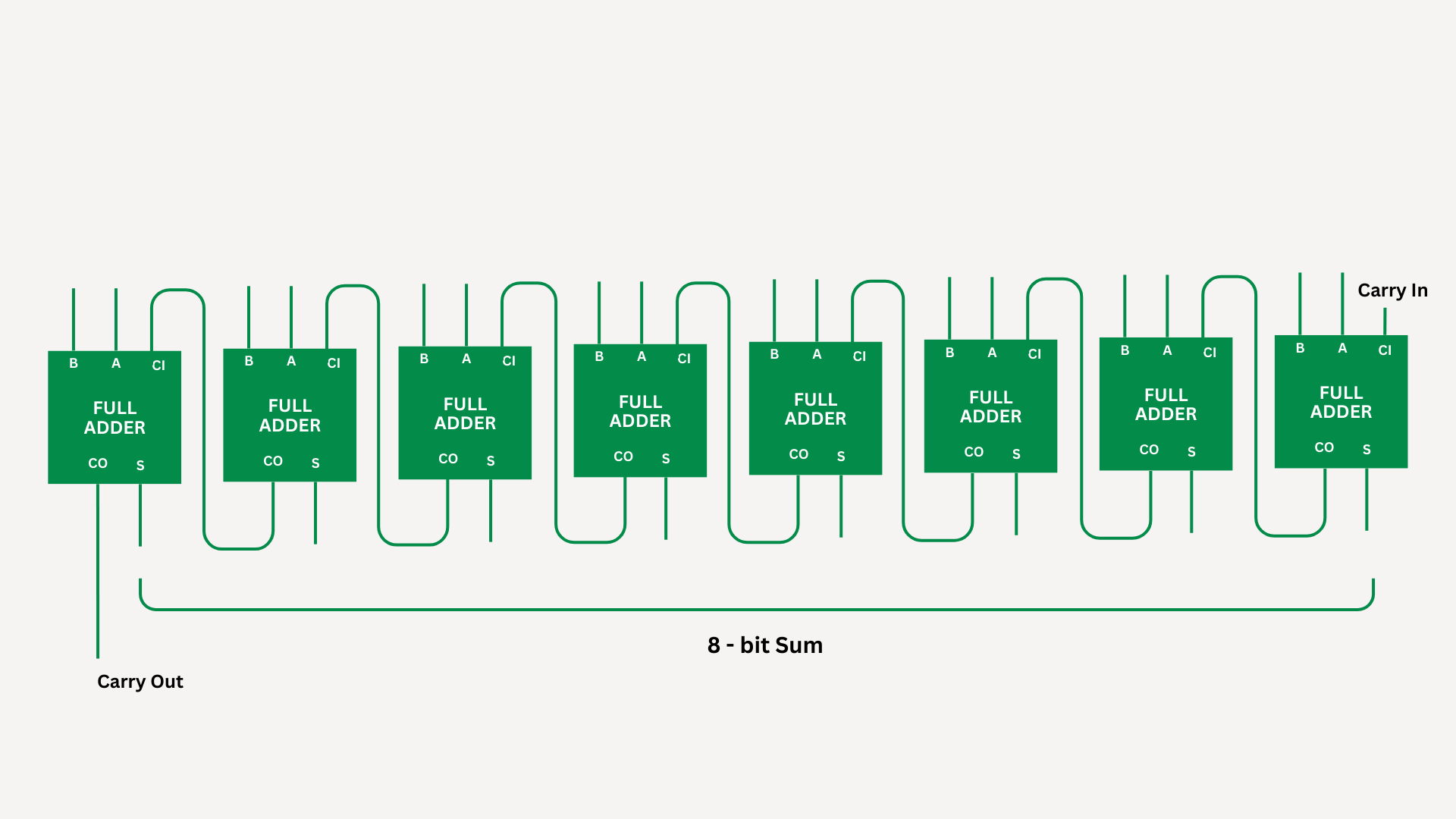
Here’s our assemblage of eight full adders with each carry-out serving as input to the next Carry In:
Conclusion
At this point, you might be thinking, “Whoa, so is this how computers do math??” Not exactly.
The basic principle demonstrated here—using full adders to perform binary addition—is indeed fundamental to how addition is performed in digital systems, including computers. However, the actual implementation in modern computers is much more complex and optimized for speed and efficiency.
In real computers, addition is typically performed in hardware using dedicated circuits called Arithmetic Logic Units (ALUs). ALUs are specifically designed to perform arithmetic operations such as addition, subtraction, multiplication, and division on binary numbers.
Modern ALUs are highly optimized and may use various techniques to improve performance, such as parallel processing, pipelining, and carry-lookahead adders. These techniques allow for faster and more efficient addition of binary numbers, critical for the high-speed processing demands of modern computing.
Additionally, computers employ various optimizations at the software level, such as using instruction sets that include specialized instructions for arithmetic operations, optimizing algorithms for addition, and leveraging hardware acceleration when available.
So while the basic concept of using full adders to perform binary addition is foundational, the actual implementation in real computers is much more sophisticated and optimized to meet the demands of modern computing.
Nonetheless, understanding these basics empowers us to grasp the inner workings of digital systems.